A fault code shown on a CNC screen does not always identify the exact component that has failed. The same is true for a status number displayed on a servo amplifier. In a multi-axis FANUC system, the CNC alarm, amplifier status, axis assignment, wiring, and test results must be analyzed together before the root cause can be confirmed.
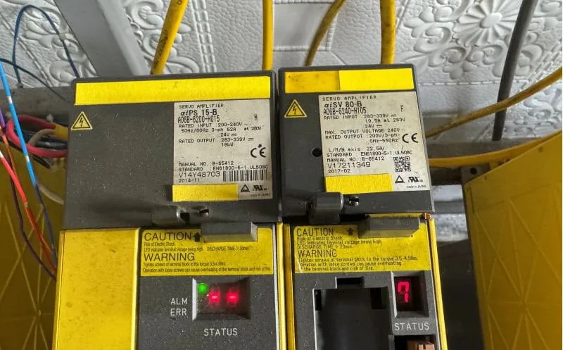
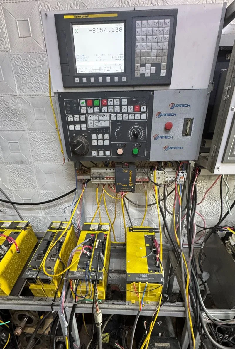
This field case involved a FANUC Series 0i-MF control that stopped with the alarm SV0654 (X) DDB RELAY FAILURE. The servo amplifier group included a FANUC A06B-6240-H105 and a FANUC A06B-6240-H115. In the site photographs, status 7 was visible on the A06B-6240-H115. However, after systematic inspection and testing, the completed repair report confirmed that the FANUC A06B-6240-H105 was the actual source of the machine fault.
This case demonstrates why maintenance teams should not replace the amplifier displaying the most obvious status indication until the entire servo system has been checked.
Case Summary
| Item | Details |
|---|---|
| CNC control | FANUC Series 0i-MF |
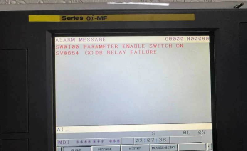
| Machine alarm | SV0654 (X) DDB RELAY FAILURE |
| Visible amplifier status | Status 7 displayed on A06B-6240-H115 |
| Confirmed fault source | FANUC A06B-6240-H105 |
1. Equipment and Fault Information
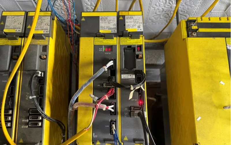
The equipment visible in the case included a FANUC Series 0i-MF CNC control, the FANUC A06B-6240-H105 servo amplifier, the adjacent FANUC A06B-6240-H115 unit, and multiple connected servo and power modules installed in the same system. For broader model sourcing, see our FANUC CNC spare parts page.
The CNC screen also showed SW0100 PARAMETER ENABLE SWITCH ON, but the SV0654 X-axis alarm was the main machine-stopping fault analyzed in this case. At the amplifier level, a status 7 was visible on the A06B-6240-H115, creating an important diagnostic challenge: was the H115 itself defective, or was its displayed status a consequence of another abnormal unit in the connected system?
The repair report provided the answer. The A06B-6240-H105, not the H115 showing status 7, was confirmed as the root fault source.
2. Why the Visible Status 7 Did Not Identify the Root Cause
A servo amplifier display is valuable diagnostic evidence, but it must be interpreted in the context of the complete CNC system. In a system containing several connected amplifiers, an abnormal condition in one unit can affect the startup, protection state, or communication status of another unit.
A neighboring amplifier may display an abnormal status when several amplifiers share related control or power conditions, when an upstream fault prevents another unit from completing startup, or when a system-level alarm causes more than one module to enter a protective state.
For this reason, the visible 7 on the A06B-6240-H115 could not be treated as proof that the H115 was defective. The correct conclusion came from the repair report and measured diagnostic results: the A06B-6240-H105 was the faulty amplifier.
3. What Does SV0654 DDB Relay Failure Mean?
The FANUC Series 0i-MF screen identified SV0654 on the X axis and described it as a DDB relay failure. This message indicates that the control detected an abnormal condition associated with the X-axis servo control or its related relay path. However, the alarm text alone does not prove that one specific relay, board, or amplifier component must be replaced.
The alarm should be used as the starting point for diagnosis, not as the final diagnosis. A qualified technician must still verify the X-axis amplifier assignment, control signals, control power, connector condition, cable condition, and whether one amplifier is preventing the system from starting normally. Machine-specific documents and official FANUC CNC support guidance should be checked alongside the actual electrical measurements.
4. Diagnostic Process Used to Isolate the H105
The photographs document the machine condition, but photographs alone cannot confirm an internal electrical failure. A reliable diagnosis requires a structured process.
Record the alarm before resetting the machine
Before cycling power or disconnecting equipment, record the complete CNC alarm message, affected axis, every amplifier status display, model numbers, serial numbers, connector positions, cable routing, LED conditions, and the operating condition immediately before the stop.
Confirm the axis-to-amplifier assignment
The CNC alarm referred to the X axis. The technician therefore had to confirm the relationship between the X axis, the A06B-6240-H105, the A06B-6240-H115, and the other installed modules. This prevents the common mistake of assuming that the amplifier with the clearest status number must be the failed component.
Check complete FANUC model numbers
A06B-6240-H105 and A06B-6240-H115 are different models. The suffix cannot be ignored when diagnosing, repairing, or sourcing a replacement. The complete model number can affect rated capacity, axis configuration, motor compatibility, hardware design, replacement compatibility, and commissioning requirements.
Inspect wiring and connectors
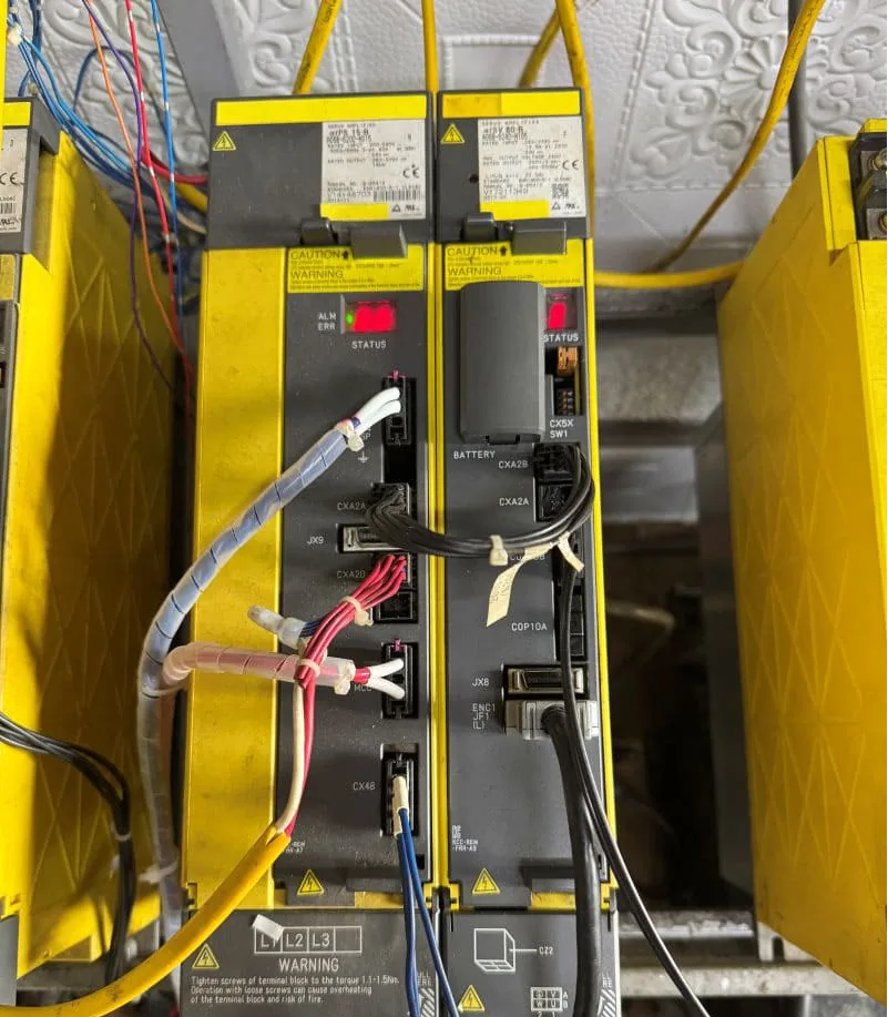
The photographs show several power and signal connections around the amplifier group. Before removing an amplifier, technicians should inspect loose plugs, damaged connector housings, oxidized contacts, broken cables, incorrectly seated feedback connectors, contamination, heat discoloration, poor grounding, and signs of previous repair.
Perform power-off electrical checks
Before applying power, relevant amplifier sections should be checked for abnormal resistance, short circuits, damaged power devices, and visible board damage. Inspection may include power input and output paths, main power devices, control power circuits, protection circuits, relay-related circuits, driver sections, PCB condition, and signs of overheating.
Use controlled power-up testing
If no severe short circuit is found, controlled power-up testing can be used to observe control voltage stability, startup sequence, DC bus behavior, amplifier status changes, abnormal current, unusual temperature rise, communication response, relay response, and whether the CNC alarm remains active.
In this case, the combined evidence confirmed that the A06B-6240-H105 caused the fault. The status 7 visible on the adjacent H115 was not sufficient to identify the root source and should not have been used as the sole reason to replace the H115.
5. Common Inspection Areas on a Faulty FANUC Servo Amplifier
The repair report identified the A06B-6240-H105 as the faulty unit, but the supplied information does not disclose the exact failed internal component. The following are common areas technicians may inspect on a FANUC servo amplifier. They are general diagnostic possibilities, not confirmed failures in this specific case.
- Control power supply: unstable or missing control voltage, aged capacitors, failed power-supply ICs, damaged diodes or MOSFETs, excessive ripple, or voltage drop under load.
- Relay and protection circuits: relay drive signals, contact condition, protection logic, associated control components, PCB tracks, solder joints, and signal continuity.
- Driver and power sections: gate-driver signals, IGBT condition, output-phase balance, driver power supplies, current-detection circuits, and heat damage.
- Feedback and communication circuits: feedback connectors, encoder-related signals, fiber or communication connections, interface circuits, cable shielding, electrical noise, and connector contamination.
- Control board: logic faults, memory or processing faults, damaged communication circuits, cracked solder joints, and contaminated PCB areas.
6. Repair or Replace the FANUC A06B-6240-H105?
Once the H105 was confirmed as the fault source, the next decision was whether to repair the existing amplifier or install a replacement. Repair may be appropriate when the damage is limited to a repairable circuit, the PCB has not suffered extensive burning, suitable components are available, and repair cost is significantly lower than replacement.
Replacement may be preferable when several major sections are damaged, the board is burned over a wide area, the unit has already undergone unsuccessful repairs, critical components are unavailable, or the required production recovery time is shorter with a replacement. For older FANUC equipment, replacement availability can be limited, so both repair support and replacement options should be evaluated before the machine is dismantled for an extended period.
7. Can an A06B-6240-H115 Replace an A06B-6240-H105?
The H105 and H115 should not be treated as interchangeable simply because they belong to the same A06B-6240 series and have a similar physical appearance. Compatibility must be checked against the complete model number, rated input and output, connected motor, axis function, CNC control configuration, hardware revision, connector arrangement, machine parameters, and FANUC replacement guidance.
Using an incorrect amplifier can result in installation problems, repeated alarms, incorrect operation, or damage to the machine. When purchasing a replacement, always provide a clear nameplate photograph and the full model number.
8. Information to Provide When Requesting a FANUC Replacement
To reduce quotation time and avoid ordering the wrong amplifier, send the supplier the complete FANUC model number, clear nameplate photograph, serial number, CNC control model, alarm-screen photograph, amplifier status photograph, affected machine axis, required quantity, preferred condition, delivery country and postal code, and required delivery time.
For this case, sending only "FANUC servo amplifier with status 7" would not have been enough. The supplier needed to know that the installed system included both A06B-6240-H105 and A06B-6240-H115 and that the repair report confirmed the H105 as the root fault source. You can also review VCOCNC shipping information and warranty options before placing an urgent order.
9. How to Reduce Similar FANUC Servo Failures
Preventive maintenance cannot eliminate every failure, but it can reduce unexpected downtime and help technicians identify developing problems earlier.
- Keep the electrical cabinet clean so metal dust, oil mist, and dirt do not reduce cooling performance or contaminate boards and connectors.
- Inspect cooling fans, air filters, ventilation openings, cabinet temperature, and heat-sink contamination.
- Check power, feedback, communication, and control cables for loose connections, damaged insulation, oil contamination, oxidation, broken shielding, excessive bending, and heat damage.
- Maintain stable incoming power, grounding, and phase condition to reduce servo alarm and component stress risk.
- Record intermittent alarms instead of ignoring them after a successful restart.
FAQ
Does status 7 always mean the amplifier showing it is defective?
No. A displayed status is an important diagnostic clue, but in a connected multi-amplifier system it may be a consequence of another fault. In this case, status 7 appeared on the A06B-6240-H115, while the repair report confirmed the A06B-6240-H105 as the actual fault source.
What was the CNC alarm in this case?
The FANUC Series 0i-MF control displayed SV0654 (X) DDB RELAY FAILURE.
Which amplifier was confirmed faulty?
The completed repair report confirmed the FANUC A06B-6240-H105 as the root fault source.
Was the A06B-6240-H115 faulty?
The supplied evidence does not confirm that the H115 was faulty. It displayed status 7, but the repair report identified the H105 as the source of the machine failure.
Can the H115 be installed in place of the H105?
It should not be assumed. Compatibility must be verified using the complete FANUC specifications, machine configuration, connected motor, and approved replacement information.
What information is needed for a quotation?
Provide the full model number, nameplate image, alarm-screen image, quantity, required condition, delivery address, and preferred delivery time.
Conclusion
This FANUC Series 0i-MF case highlights an important troubleshooting principle: the most visible alarm indication is not always the root cause. The machine displayed SV0654 (X) DDB RELAY FAILURE. The A06B-6240-H115 visibly showed status 7, but the completed repair report confirmed that the FANUC A06B-6240-H105 was the actual source of the fault.
A reliable diagnosis should combine CNC alarm information, axis assignment, complete amplifier model numbers, wiring and connector inspection, controlled electrical testing, and final repair-report evidence.
If you need a FANUC A06B-6240-H105 or another FANUC CNC spare part, request a quote with the complete model number, a clear nameplate photograph, the alarm-screen image, quantity, and delivery location.